Well the laptop is still working..
Now doesn't this newly released video demonstating the new FUNCubeDongle PRO+ make your mouth water?
Friday, 28 September 2012


Thursday, 27 September 2012
If at first you don't succeed... try, try, try again
Hopefully yesterday saw the conclusion to the saga of my broken laptop.
Two weeks ago I had an attempt at reviving a sickly HP/Compaq 6735S a model which is notorious for GPU problems. Specifically the GPU BGA contacts break due to thermal stresses and shoddy manufacturing.
I had stripped the laptop down and using a IR rework station attempted to reflow the contacts with limited success. It survived one power up and then died again.
Like Robbie Burn's famous spider I was not going to give up that easily so I stripped it down again and this time remembering the 7 Ps adage I didn't cut any corners.

The picture above shows the motherboard after I removed it the first time, you can clearly see the GPU in the top right. Notice first the pathetic thermal bonding? Also you can see around all four corners of the chip what appears to be red cement.
Initially I was unsure of whether to remove this and indeed it appeared to be tough and nigh on impossible to remove so fearing possible collateral damage I left the cement in place and heated the GPU on the IR rework station attempting to reflow the joints.
This I believe was the mistake as this bonding would have prevent the chip from floating on the reflowed solder pads. So this time I did remove the cement as you can see below. I found heating the cement did make it malleable, the problem being how to heat it without damaging any of the surrounding components?
In the end I used a precision hot-air gun (which they also have at work) on a low-medium heat setting on a very low 'blow' setting. Using this and a couple of wooden toothpicks I was able to remove the vast majority of the red gunk!
Once removed I applied a small amount of flux around the chip, working it under the device and then used the IR rework station but on a much higher setting than before to ensure the solder properly melted.

To my pleasant surprise the reassembled laptop booted and it has been successfully been powered down and rebooted several more times since.

While not the prettiest of laptops, or indeed in the best condition it does at least have Windows 7 Professional on it and a nice big hard drive and 4GB of memory so should prove more than capable for my experiments - assuming she carries on working, and she does get a little warm!
Two weeks ago I had an attempt at reviving a sickly HP/Compaq 6735S a model which is notorious for GPU problems. Specifically the GPU BGA contacts break due to thermal stresses and shoddy manufacturing.
I had stripped the laptop down and using a IR rework station attempted to reflow the contacts with limited success. It survived one power up and then died again.
Like Robbie Burn's famous spider I was not going to give up that easily so I stripped it down again and this time remembering the 7 Ps adage I didn't cut any corners.

The picture above shows the motherboard after I removed it the first time, you can clearly see the GPU in the top right. Notice first the pathetic thermal bonding? Also you can see around all four corners of the chip what appears to be red cement.
Initially I was unsure of whether to remove this and indeed it appeared to be tough and nigh on impossible to remove so fearing possible collateral damage I left the cement in place and heated the GPU on the IR rework station attempting to reflow the joints.
This I believe was the mistake as this bonding would have prevent the chip from floating on the reflowed solder pads. So this time I did remove the cement as you can see below. I found heating the cement did make it malleable, the problem being how to heat it without damaging any of the surrounding components?
In the end I used a precision hot-air gun (which they also have at work) on a low-medium heat setting on a very low 'blow' setting. Using this and a couple of wooden toothpicks I was able to remove the vast majority of the red gunk!
Once removed I applied a small amount of flux around the chip, working it under the device and then used the IR rework station but on a much higher setting than before to ensure the solder properly melted.

To my pleasant surprise the reassembled laptop booted and it has been successfully been powered down and rebooted several more times since.

While not the prettiest of laptops, or indeed in the best condition it does at least have Windows 7 Professional on it and a nice big hard drive and 4GB of memory so should prove more than capable for my experiments - assuming she carries on working, and she does get a little warm!
Tuesday, 25 September 2012
FUNcube Dongle PRO+
Ever since I got my FUNCube Dongle Pro last Christmas it has been the main focus of my radio experimentation. I have used it on a number of computers including some quite old not very powerful machines and with different software applications primarily the SDR-Radio and HDSDR suites.
It was a little fiddly to initially set up but I have been impressed with its performance, it has opened my eyes and ears to what is out there on VHF and UHF, much more than I could ever monitor using my scanner receivers. Have a look at my previous postings.
Being SDR, with all decoding being done in software, it is effectively capable of all modes capable with the added advantage of having a variable bandwidth which is useful for data modes.
I have decoded images broadcast from orbit, received transmissions relayed via satellite and even bounced off the surface of the moon! As well as listening to all manner of terrestrial broadcasts.
In a word it is BRILLIANT.
It has its faults, or should I say limitations. It would be nice to have more of the spectrum available at one time and the front end filtering and rejection is troublesome at times. However this is more than made up for by its versatility and performance and it often out preforms my PRO2006 on the same antenna.
On the various forums and social networks it irks me to see people complaining about its performance but then they are usually the same people who go out and purchase a sub £20 RTL2832U based USB FM/DAB/DTV receiver dongle from eBay to use as a SDR and then complain they cannot get it to work or that its performance is lacking. But then that seems to quite common at the moment, everyone expects to just plug it in and it to just work with the minimum of understanding, involvement or experimentation but I digress.
Unfortunately Elonics the suppliers of the tuner chip in the FUNCube Dongle PRO are currently in liquidation and so they have struggled to produce any more units since July this year. This has potentially serious implications for the whole FUNCube educational project as there is no earth based component. Therefore the FUNCube team have instigated a redesign of the receiver and in doing so have increased its functionality and addressed some of the issues. This is the FUNCube Dongle PRO+

The new FUNcube Dongle Pro+ offers the following features and enhancements:
The official release of the FUNcube Dongle PRO+ was made during a presentation given to the AMSAT-UKInternational Space Colloquium 2012 on Saturday September 15. You can view the presentation by following these steps:
- Go to http://www.batc.tv/
- Click on "Film Archive"
- Select "AMSAT 2012" in Category box and click on Select Category
- Select "02 - FUNcube PRO-PLUS" in Stream box and click on Select Stream
Or download the whole video of the presentation from
http://www.batc.tv/vod/AMSAT%20session2.flv
It was a little fiddly to initially set up but I have been impressed with its performance, it has opened my eyes and ears to what is out there on VHF and UHF, much more than I could ever monitor using my scanner receivers. Have a look at my previous postings.
Being SDR, with all decoding being done in software, it is effectively capable of all modes capable with the added advantage of having a variable bandwidth which is useful for data modes.
I have decoded images broadcast from orbit, received transmissions relayed via satellite and even bounced off the surface of the moon! As well as listening to all manner of terrestrial broadcasts.
In a word it is BRILLIANT.
It has its faults, or should I say limitations. It would be nice to have more of the spectrum available at one time and the front end filtering and rejection is troublesome at times. However this is more than made up for by its versatility and performance and it often out preforms my PRO2006 on the same antenna.
On the various forums and social networks it irks me to see people complaining about its performance but then they are usually the same people who go out and purchase a sub £20 RTL2832U based USB FM/DAB/DTV receiver dongle from eBay to use as a SDR and then complain they cannot get it to work or that its performance is lacking. But then that seems to quite common at the moment, everyone expects to just plug it in and it to just work with the minimum of understanding, involvement or experimentation but I digress.
Unfortunately Elonics the suppliers of the tuner chip in the FUNCube Dongle PRO are currently in liquidation and so they have struggled to produce any more units since July this year. This has potentially serious implications for the whole FUNCube educational project as there is no earth based component. Therefore the FUNCube team have instigated a redesign of the receiver and in doing so have increased its functionality and addressed some of the issues. This is the FUNCube Dongle PRO+
The new FUNcube Dongle Pro+ offers the following features and enhancements:
- Full coverage of all amateur bands from 136kHz through HF, 6m, 2m, 4m, 2m, 1.25m, 70cm, 33cm, 23cm (150kHz-240MHz and 420MHz-1.9GHz, 70kHz-150kHz coverage through your software’s NCO offset)
- 0.5ppm TCXO
- 192kHz sampling rate
- Eleven discrete front end filters
- Super sharp SAW filters on 2m and 70cm
The official release of the FUNcube Dongle PRO+ was made during a presentation given to the AMSAT-UKInternational Space Colloquium 2012 on Saturday September 15. You can view the presentation by following these steps:
- Go to http://www.batc.tv/
- Click on "Film Archive"
- Select "AMSAT 2012" in Category box and click on Select Category
- Select "02 - FUNcube PRO-PLUS" in Stream box and click on Select Stream
Or download the whole video of the presentation from
http://www.batc.tv/vod/AMSAT%20session2.flv
Saturday, 22 September 2012
Gahhh! I didn't fix the laptop
I spoke too soon I finally got hold of some thermal paste and reassembled the laptop. Everything looked fine it powered up and had installed all the latest windows and software updates it had missed during it's illness.
I closed the lid when I'd finished then when I opened the lid to use it again and it won't power up! Flashes the cap lock LED five times to indicate the same fault!
Piece of s.....
Thursday, 20 September 2012
ARISS Contact 19th September 2012
I did manage to get a decent capture of the ISS downlink during the ARISS School Contact on Wednesday morning before I had to leave for work. It was a bit cold standing out with the antenna but was worth it.
ARISS School Contact 19-Sep-2012 by nerdsville
ARISS School Contact 19-Sep-2012 by nerdsville
Tuesday, 18 September 2012
Two more ARISS downlink recordings
Seems to be lots of ARISS activity at the moment. There have been a number of school contacts over the last few weeks that have had downlink transmission from the International Space Station receivable over the UK and Europe. Tomorrow morning (September 19th) there is another one, but it is unlikely I will be able to have a proper attempt at receiving it.
However these are the last two downlink transmissions I managed to receive.
ARISS School Contact 09-Sep-2012 by nerdsville
ARISS School Contact 13-Sep-2012 by nerdsville
On a related note found this video today that made me smile can you spot the deliberate mistake?
However these are the last two downlink transmissions I managed to receive.
ARISS School Contact 09-Sep-2012 by nerdsville
ARISS School Contact 13-Sep-2012 by nerdsville
On a related note found this video today that made me smile can you spot the deliberate mistake?
Wednesday, 12 September 2012
Fixing my broken laptop
Last Saturday saw a huge tropospheric lift on VHF and UHF. The amateur bands
were apparently buzzing with activity and scanner enthusiasts were reporting lots of new signals.
Unfortunately I wasn't at home so missed most of the action.
However I did manage to have a Sunday to tinker to my hearts content, I will post up some details of what I got up to when I have more time. I did get an excellent capture of the ISS downlink for the ARISS school contact and did some experiments with receiving some UHF Satcom stuff.
One thing I finally got around to doing was removing the motherboard from a sick laptop. It is a HP/Compaq laptop and suddenly died one evening. It would no longer boot and flashing a diagnostic code on one of the LEDs. The code was "GENERAL SYSTEM BOARD FAILURE". The laptop is quite nice and was going to form a key component of the shack and so I was determined to repair it if necessary.
I did some googling and it seems the model in question is prone to failure of the GPU, or more specifically failure of the contacts between the GPU and motherboardl. This is a common fault now in many devices especially those with components that run hot (Xbox/PS3 etc)
It is thought that the temperature and thermal stresses involved cause one or more of the contacts to break. On inspection of the heat sink over the GPU and CPU I was shocked at the poor mounting and application of thermal pads/paste which undoubtedly made the problem worse.
The suspected faulty GPU is mounted using a ball grid array, where the contacts are under the component the problem with this is you cannot easily repair or replace the contact without specialist equipment. What is required is to reflow the solder joints, heating up the component sufficient so the solder underneath melts reforming the contact.
Several methods of 'homebrew' repair are available using heat guns, blow lamps or placing the board in a hot oven but due to the delicate nature of the board and risk to surrounding components aren't recommended.
As luck would have it I had access to a Infra-red rework station, this device has a high intensity infra-red lamp which heats the component and a heat pad underneath to pre-heat the circuit board. The advantage of this is there is no risk of movement to the components during the process and the temperature can be accurately controlled.
Well I had a go, and can report the motherboard is now working or at least now boots up. I just now have to replace the thermal bonding under the heat sink to hopefully prevent it happening again and then the small matter of putting it all back together!
However I did manage to have a Sunday to tinker to my hearts content, I will post up some details of what I got up to when I have more time. I did get an excellent capture of the ISS downlink for the ARISS school contact and did some experiments with receiving some UHF Satcom stuff.
One thing I finally got around to doing was removing the motherboard from a sick laptop. It is a HP/Compaq laptop and suddenly died one evening. It would no longer boot and flashing a diagnostic code on one of the LEDs. The code was "GENERAL SYSTEM BOARD FAILURE". The laptop is quite nice and was going to form a key component of the shack and so I was determined to repair it if necessary.
I did some googling and it seems the model in question is prone to failure of the GPU, or more specifically failure of the contacts between the GPU and motherboardl. This is a common fault now in many devices especially those with components that run hot (Xbox/PS3 etc)
It is thought that the temperature and thermal stresses involved cause one or more of the contacts to break. On inspection of the heat sink over the GPU and CPU I was shocked at the poor mounting and application of thermal pads/paste which undoubtedly made the problem worse.
The suspected faulty GPU is mounted using a ball grid array, where the contacts are under the component the problem with this is you cannot easily repair or replace the contact without specialist equipment. What is required is to reflow the solder joints, heating up the component sufficient so the solder underneath melts reforming the contact.
Several methods of 'homebrew' repair are available using heat guns, blow lamps or placing the board in a hot oven but due to the delicate nature of the board and risk to surrounding components aren't recommended.
As luck would have it I had access to a Infra-red rework station, this device has a high intensity infra-red lamp which heats the component and a heat pad underneath to pre-heat the circuit board. The advantage of this is there is no risk of movement to the components during the process and the temperature can be accurately controlled.
Well I had a go, and can report the motherboard is now working or at least now boots up. I just now have to replace the thermal bonding under the heat sink to hopefully prevent it happening again and then the small matter of putting it all back together!
Friday, 7 September 2012
Some reception reports
Not much to report, but have had a few decent monitoring sessions with the FUNCube Dongle.
A couple of ISS ARISS School Contacts took place over Europe during the last couple of weeks, with another taking place on Sunday morning. I was in work during the passes but managed to remotely log in to my computer to do some 'unattended' SDR-Radio recordings.
ARISS School Contact 31-Aug-2012 by nerdsville
ARISS School Contact 07-Sep-2012 by nerdsville
Late last night there was a bit of a lift on VHF and managed to receive the GB3VHF 144MHz Beacon which while it may not seem very news worthy is given there is a huge hill in the way when you look towards Kent! I have received it before using the Yagi in an horizontal polarization. But last nights reception was via the discone in the loft, which was a first. Love the JT65B tones, very musical.
GB3VHF by nerdsville
Earlier last night was also quite amusing when I stumbled across the Hucknall Rolls-Royce Amateur Radio Club who were trying to run an Amateur Radio Direction Finding Fox-hunt but were being completely blotted out by another, seemingly deaf, local operator pumping out 100W, though he did turn it down to 10W eventually.
Amateur Radio Direction Finding - Or Not! by nerdsville
Finally last weekend was the RSGB 144MHz Trophy Contest, again I got to get some decent SSB reception.
144MHz Trophy Contest - Part 1 by nerdsville
144MHz Trophy Contest - Part 2 by nerdsville
A couple of ISS ARISS School Contacts took place over Europe during the last couple of weeks, with another taking place on Sunday morning. I was in work during the passes but managed to remotely log in to my computer to do some 'unattended' SDR-Radio recordings.
ARISS School Contact 31-Aug-2012 by nerdsville
ARISS School Contact 07-Sep-2012 by nerdsville
Late last night there was a bit of a lift on VHF and managed to receive the GB3VHF 144MHz Beacon which while it may not seem very news worthy is given there is a huge hill in the way when you look towards Kent! I have received it before using the Yagi in an horizontal polarization. But last nights reception was via the discone in the loft, which was a first. Love the JT65B tones, very musical.
GB3VHF by nerdsville
Earlier last night was also quite amusing when I stumbled across the Hucknall Rolls-Royce Amateur Radio Club who were trying to run an Amateur Radio Direction Finding Fox-hunt but were being completely blotted out by another, seemingly deaf, local operator pumping out 100W, though he did turn it down to 10W eventually.
Amateur Radio Direction Finding - Or Not! by nerdsville
Finally last weekend was the RSGB 144MHz Trophy Contest, again I got to get some decent SSB reception.
144MHz Trophy Contest - Part 1 by nerdsville
144MHz Trophy Contest - Part 2 by nerdsville
Friday, 24 August 2012
Shack Update

Again it has been a very busy month since my last post, but I did manage to get a few days to finally start sorting out my workshop/shack.
Just before the horrendous winter of 2010 struck I had purchased a 16' x 10' wooden workshop, in fact you can see it in the picture below the day after it was erected complete with a coating of snow! The workshop was subdivided into two separate sections a smaller 6' x 10' area with it's own door for storage of garden paraphernalia and the remaining 10' x 10' section was intended to be a 'man cave' where I could keep my junk, set up a small workspace and experiment to my heart's content without an accountability. The intention was to free up a small bedroom in the house and remove some of the accumulated junk from the loft!
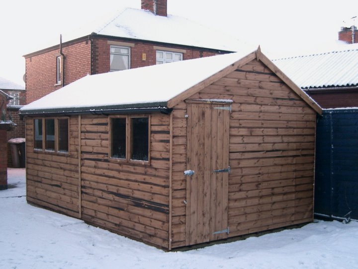
Well for the past 18 months despite my best intentions the workshop had become nothing but yet another store room! The first task was to empty the workshop and sort out the rubbish, almost immediately I became rather dispirited as it seemed a huge task, however after several temper tantrums, a beer or two and some ruthless decisions followed by several trips to the local tip I had got rid of a large portion of the contents.The remaining good stuff including tools, screws, nails and other items were sorted roughly into boxes to be properly organised at a later date.
I had already run an armoured electrical cable supply into the workshop but no internal wiring. The distribution/RCD unit, cabling, sockets, switches and lighting were still sitting in the screwfix box. Several hours of hard work in the sweltering heat and I had it wired it up with some decent lighting and power sockets. I also took the opportunity to install some
proper thick moisture resistant chipboard tongue and groove flooring to strengthen the existing floor and
that has been covered in some vinyl flooring for ease of cleaning.

I had always intended to line out the workshop with plywood and insulate it but I had a change of heart, mostly due to cost but also for aesthetic reasons since it has a lovely rustic wooden feel inside with roof beams and the tongue and groove panelling, I will probably regret the decision in the winter, but given the fact that everything stored in it has survived two harsh winters with no signs of damp I have left it alone for now.
I have furnished it with some unwanted items including a nice sturdy table, chest of draws and some old book shelves and have gradually been moving my junk into the workshop. I am now in the process of sorting out some more shelving and a soldering station and workbench so I can finally start tinkering again!
I have also installed a wireless access point configured using WDS to connect to the main house WLAN and that seems to be reasonably fast and reliable and have an old PC which gives me access to the Internet and my music library I can listen to without being told to turn it down!
I should add the whole shed/workshop are protected by a proper security alarm with PIR and door contact sensors.
Sunday, 15 July 2012
Experiments with an SDR4+ and a scanner refurb
Seems the holiday in early June broke the blogging momentum and unfortunately work commitments since and the stresses involved as a major project nears deployment have sapped my time and energy, so not had much to post.
Family commitments too have also eaten into my spare time not leaving me time or inclination to experiment. The FUNCube Dongle and the Ultra-cheap RTL-SDR have been unplugged for several weeks and I am ashamed to say most of my evenings have been sent slumped in front of the TV often nodding off to sleep rather than tinkering away.
That is not to say I have been completely idle! I have spent the last couple of weeks with a Cross Country Wireless SDR4+ receiver courtesy of my younger brother. For a while I have toyed with purchasing one after seeing them at last years Hamfest and have read some decent reviews. The SDR4+ is a HF Software Defined Radio covering 0.85 - 30MHz, the full specifications can be found on their website.
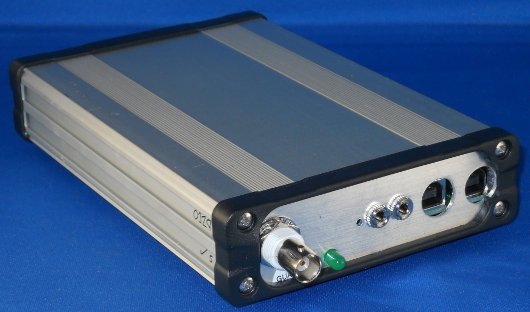
My brother shares a similar interest in radio, probably as he was forced to share a room with me when we were younger and I would subject him to listening to all sorts of strange signals late into the night! Well he decided to purchase one several weeks ago, but was frustrated when it didn't seem to work. On one of visits to see my Mother I took a cursory look and couldn't make it work either. To cut a long story short while he went away on holiday I borrowed the unit away to see if I could figure it out.
Following some experimentation and discussions with Chris Moulding on the Cross Country Wireless Yahoo Group turned out the problem was some dodgy USB ports and/or USB leads! The thread can be read at http://uk.groups.yahoo.com/group/cross_country_wireless/message/2136
I strung up a long random-length wire antenna in the loft and have managed to get some decent results on some bands, but interestingly very little on others, probably due to the lack of an ATU. But I have received lots of broadcast AM, some DRM (but not actually decoded) and buckets loads of Amateur transmissions, LSB/USB voice and Morse, RTTY and PSK31 from Europe, and decoded some HF-FAX. Sadly the SDR4+ will soon be off back to it's rightful owner, but has certainly wetted my appetite.
I have also refurbished my Realistic PRO2022 scanner, as I posted back in 2010 this was my very first scanner and sadly was looking a little bit worse for years of wear. It is still functional, especially for listening to airband but the displays electro-luminescence back light had faded and it was looking a little grubby.


I found a cheap supplier of a suitable EL panel on Ebay and quickly had the new one cut to size and fitted, giving a lovely new blue display.

The next thing was to clean the grime and grease that was encrusted on the case and knobs, using a small amount of Clit-Bang degreaser and being very careful soon had the case looking almost as good as new!

Family commitments too have also eaten into my spare time not leaving me time or inclination to experiment. The FUNCube Dongle and the Ultra-cheap RTL-SDR have been unplugged for several weeks and I am ashamed to say most of my evenings have been sent slumped in front of the TV often nodding off to sleep rather than tinkering away.
That is not to say I have been completely idle! I have spent the last couple of weeks with a Cross Country Wireless SDR4+ receiver courtesy of my younger brother. For a while I have toyed with purchasing one after seeing them at last years Hamfest and have read some decent reviews. The SDR4+ is a HF Software Defined Radio covering 0.85 - 30MHz, the full specifications can be found on their website.
My brother shares a similar interest in radio, probably as he was forced to share a room with me when we were younger and I would subject him to listening to all sorts of strange signals late into the night! Well he decided to purchase one several weeks ago, but was frustrated when it didn't seem to work. On one of visits to see my Mother I took a cursory look and couldn't make it work either. To cut a long story short while he went away on holiday I borrowed the unit away to see if I could figure it out.
Following some experimentation and discussions with Chris Moulding on the Cross Country Wireless Yahoo Group turned out the problem was some dodgy USB ports and/or USB leads! The thread can be read at http://uk.groups.yahoo.com/group/cross_country_wireless/message/2136
I strung up a long random-length wire antenna in the loft and have managed to get some decent results on some bands, but interestingly very little on others, probably due to the lack of an ATU. But I have received lots of broadcast AM, some DRM (but not actually decoded) and buckets loads of Amateur transmissions, LSB/USB voice and Morse, RTTY and PSK31 from Europe, and decoded some HF-FAX. Sadly the SDR4+ will soon be off back to it's rightful owner, but has certainly wetted my appetite.
I have also refurbished my Realistic PRO2022 scanner, as I posted back in 2010 this was my very first scanner and sadly was looking a little bit worse for years of wear. It is still functional, especially for listening to airband but the displays electro-luminescence back light had faded and it was looking a little grubby.

I had already replaced the backlight on my PRO2006, but this was a lot easier due to the display being easily accessible with the simple removal of the front panel, and the EL panel being on flying leads rather than soldered on to a PCB.


I found a cheap supplier of a suitable EL panel on Ebay and quickly had the new one cut to size and fitted, giving a lovely new blue display.

The next thing was to clean the grime and grease that was encrusted on the case and knobs, using a small amount of Clit-Bang degreaser and being very careful soon had the case looking almost as good as new!

Friday, 8 June 2012
Skelton Transmitter Site
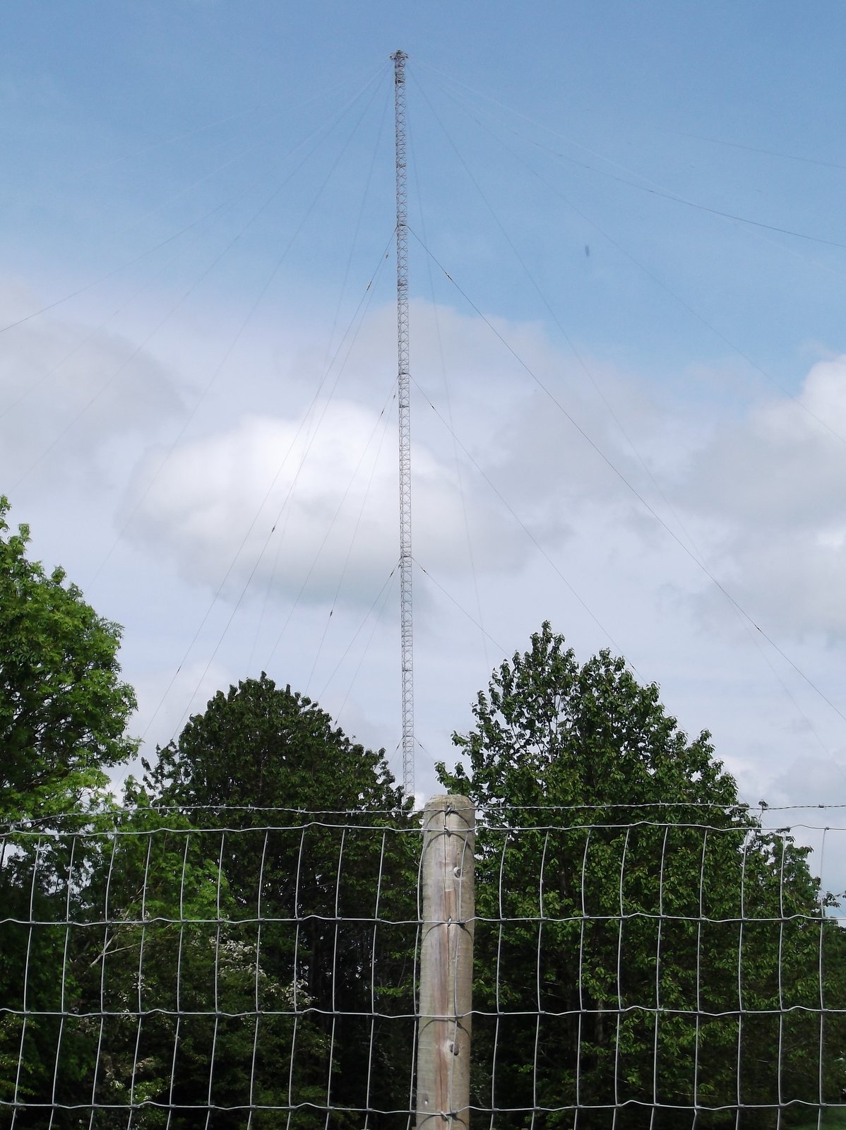
Just spent the last week in Cumbria and the Lake District on holiday, for part of the time we were camped near the village of Skelton around 5 miles north west of Penrith. Skelton is famous for it's huge transmitter site. The primary function is shortwave broadcasting, but it also supposed to be the site of a VLF array used for communication with submarines.
While out finding some geocaches I managed to take a few photos of the impressive antenna arrays.


While out finding some geocaches I managed to take a few photos of the impressive antenna arrays.


Tuesday, 22 May 2012
RTLSDR - Part 4 - Cutting out the noise using a simple coax filter
One major limitation of both the FUNCube Dongle and the RTL-SDR based receivers is the poor front end filtering.
Connecting a wide band antenna such as a discone to the input often results in a spectrum full of noise which swamps the target signal.
In most cases the noise is actually a result of out of band high-power transmissions such as FM and TV broadcast stations and pagers which overload the receiver and get mixed in to the tuned signal. The effects can be mitigated to a degree by turning down the gain of the receiver but at the expense of sensitivity to the signal you are wanting to receive.
The FUNCube Dongle in my experience seems especially susceptible to the effects of FM broadcast signals when trying to monitor the 2-Meter amateur band. I'm not sure if the current weather conditions were the cause but yesterday evening it seemed the breakthrough was especially bad. So I decided to experiment with a simple coax 'notch' filter.
There are two approaches to filtering, one is to use a band-pass filter which passes frequencies within a certain range and rejects (attenuates) frequencies outside that range. The other is to use a band-stop filter that passes most frequencies unaltered, but attenuates those in a specific range to very low levels. A notch filter is a band-stop filter with a narrow stop band.
As it happens you can make an effective filter using ordinary coaxial cable which will generate a sharp, deep notch which can be used to attenuate the unwanted signal.
A coax stub notch filter can be made if you connect the antenna to the receiver using a T-connector then attach a piece of coax of the appropriate length (the stub) to the remaining connector.
I happen to have a fair bit of 10Base2 Thin-Ethernet cabling (RG-58U) and connectors which were repatriated from a previous employer over a decade ago. The network cards they used came supplied with lovely long high quality 10m patch leads with moulded BNC connectors and a T-Connector and terminator! Even back then the 10Base2 was completely redundant as the network infrastructure used Cat-5 cabling.
So I dug out one of the T-Connectors and a BNC connector and set to work, connecting the antenna and receiver was simple, all I needed was to construct the coax stub.
To calculate the length of the stub you must first calculate the wave length of the desired 'notch frequency' for the FM band a good central notch frequency is around 100MHz.
The wave length is found by dividing the speed of light (which is around 300,000km/sec in free space) by frequency
So for a 100MHz signal the wave length is 300/100 = 3 meters.
However the speed of the radio wave in a coax is affected by the material it is made of, this is called the velocity factor. For most solid polyethylene coax (e.g RG-58) this is 66% (a handy table can be found here)
So multiplying 3 x 0.66 = 1.98 meters
The coax stub is 1/4 of this wavelength = 1.98 x 0.25 = 0.495 (49.5 cm)
So cutting a piece of coax of that length, connecting it to the T-Connector and leaving the other end open completes the filter. The filter will have maximum attenuation at 100MHz (assuming the coax is cut accurately) and the attenuation will fall off away from this 'notch frequency' (Note the filter will also notch at 300MHz, 500MHz and so on)
Interestingly it seems my RTL based SDR receiver is more affected by pager breakthrough, so I plan to make an alternative stub, adjusting the calculation to use 153MHz as the notch frequency to reduce this. It is possible to add more than one filter at a time using multiple T-Connectors and alternative higher performance designs for coax notch and band-pass filters can be found with a quick Google search.
I made a quick video showing the effectiveness of this simple filter which took about 10 minutes to make!
Connecting a wide band antenna such as a discone to the input often results in a spectrum full of noise which swamps the target signal.
In most cases the noise is actually a result of out of band high-power transmissions such as FM and TV broadcast stations and pagers which overload the receiver and get mixed in to the tuned signal. The effects can be mitigated to a degree by turning down the gain of the receiver but at the expense of sensitivity to the signal you are wanting to receive.
The FUNCube Dongle in my experience seems especially susceptible to the effects of FM broadcast signals when trying to monitor the 2-Meter amateur band. I'm not sure if the current weather conditions were the cause but yesterday evening it seemed the breakthrough was especially bad. So I decided to experiment with a simple coax 'notch' filter.
There are two approaches to filtering, one is to use a band-pass filter which passes frequencies within a certain range and rejects (attenuates) frequencies outside that range. The other is to use a band-stop filter that passes most frequencies unaltered, but attenuates those in a specific range to very low levels. A notch filter is a band-stop filter with a narrow stop band.
As it happens you can make an effective filter using ordinary coaxial cable which will generate a sharp, deep notch which can be used to attenuate the unwanted signal.
A coax stub notch filter can be made if you connect the antenna to the receiver using a T-connector then attach a piece of coax of the appropriate length (the stub) to the remaining connector.
I happen to have a fair bit of 10Base2 Thin-Ethernet cabling (RG-58U) and connectors which were repatriated from a previous employer over a decade ago. The network cards they used came supplied with lovely long high quality 10m patch leads with moulded BNC connectors and a T-Connector and terminator! Even back then the 10Base2 was completely redundant as the network infrastructure used Cat-5 cabling.
So I dug out one of the T-Connectors and a BNC connector and set to work, connecting the antenna and receiver was simple, all I needed was to construct the coax stub.
To calculate the length of the stub you must first calculate the wave length of the desired 'notch frequency' for the FM band a good central notch frequency is around 100MHz.
The wave length is found by dividing the speed of light (which is around 300,000km/sec in free space) by frequency
So for a 100MHz signal the wave length is 300/100 = 3 meters.
However the speed of the radio wave in a coax is affected by the material it is made of, this is called the velocity factor. For most solid polyethylene coax (e.g RG-58) this is 66% (a handy table can be found here)
So multiplying 3 x 0.66 = 1.98 meters
The coax stub is 1/4 of this wavelength = 1.98 x 0.25 = 0.495 (49.5 cm)
So cutting a piece of coax of that length, connecting it to the T-Connector and leaving the other end open completes the filter. The filter will have maximum attenuation at 100MHz (assuming the coax is cut accurately) and the attenuation will fall off away from this 'notch frequency' (Note the filter will also notch at 300MHz, 500MHz and so on)
Interestingly it seems my RTL based SDR receiver is more affected by pager breakthrough, so I plan to make an alternative stub, adjusting the calculation to use 153MHz as the notch frequency to reduce this. It is possible to add more than one filter at a time using multiple T-Connectors and alternative higher performance designs for coax notch and band-pass filters can be found with a quick Google search.
I made a quick video showing the effectiveness of this simple filter which took about 10 minutes to make!
Monday, 21 May 2012
Some audio from the 144MHz SSB Contest
Not had much radio time since Saturday due to family duties but did managed to find time to edit down some of the audio from the 144MHz SSB Amateur Radio Contest I received.
The first part of the audio was from the FUNCube Dongle, the latter part from the Ultra cheap NewSky DVB-T stick running the RTL-SDR driver.
Both were received using the loft mounted discone antenna which I believe is vertically polarised and so wasn't optimal since SSB is broadcast using horizontal polarization. Even so I was quite impressed with what I did receive with such humble equipment.The stations calling in the audio were G0VHF (morse and voice), M0KWP, M0BAA, 2E0KWM and G4SIV
144MHZ SSB Contest by nerdsville
Please note the corruption that can be heard toward the end of audio appears to be an artifact of the sound editor and/or the transcoding used by soundcloud as it wasn't in the original audio.
The first part of the audio was from the FUNCube Dongle, the latter part from the Ultra cheap NewSky DVB-T stick running the RTL-SDR driver.
Both were received using the loft mounted discone antenna which I believe is vertically polarised and so wasn't optimal since SSB is broadcast using horizontal polarization. Even so I was quite impressed with what I did receive with such humble equipment.The stations calling in the audio were G0VHF (morse and voice), M0KWP, M0BAA, 2E0KWM and G4SIV
144MHZ SSB Contest by nerdsville
Please note the corruption that can be heard toward the end of audio appears to be an artifact of the sound editor and/or the transcoding used by soundcloud as it wasn't in the original audio.
Sunday, 20 May 2012
RTLSDR - Part 3 - CQ CQ Contest
As it's the weekend I have managed to experiment with my new SDR device. I have sorted out an adapter so I can connect it to the loft discone and it has been pulling in some very nice clear signals. I have had to do some tweaking especially of the usb transfer buffer size to get some decent audio out of it. I have also had to learn how to use the HDSDR program which I haven't used much before favouring the SDR-Radio one with the FUNCube Dongle.
One thing that caught me out is that when I last used HDSDR with the FUNCube I had to swap the I and Q signals and I don't need to with the Newsky Tv28t so initially I was very confused as it all seem arse about face! Duh! But now actually growing to quite like it as having a much wider spectrum to see is very nice.
By a pleasant coincidence yesterday saw the start of the RSGB 144MHz May Contest so lots of SSB transmissions to tune in to. The FUNCube definitely has the edge when it comes to quality of audio and sensitivity and being able to tune down the gain helps in preventing out of band signal overloading the front end. With the Newsky device I've had to have the gain right up most of the time, but I suspect there is still more optimising to do.
Just a small video showing some of the SSB Contest signals on the spectrum. Don't you just love the masses of noise? Really must do something about that damn router!
I've also got to discover how to calibrate the Newsky as it shows quite a bit off frequency, I understand I need to discover the actual crystal clock frequency and can feed that into the EXT-IO plugin.
One thing that caught me out is that when I last used HDSDR with the FUNCube I had to swap the I and Q signals and I don't need to with the Newsky Tv28t so initially I was very confused as it all seem arse about face! Duh! But now actually growing to quite like it as having a much wider spectrum to see is very nice.
By a pleasant coincidence yesterday saw the start of the RSGB 144MHz May Contest so lots of SSB transmissions to tune in to. The FUNCube definitely has the edge when it comes to quality of audio and sensitivity and being able to tune down the gain helps in preventing out of band signal overloading the front end. With the Newsky device I've had to have the gain right up most of the time, but I suspect there is still more optimising to do.
Just a small video showing some of the SSB Contest signals on the spectrum. Don't you just love the masses of noise? Really must do something about that damn router!
I've also got to discover how to calibrate the Newsky as it shows quite a bit off frequency, I understand I need to discover the actual crystal clock frequency and can feed that into the EXT-IO plugin.
Friday, 18 May 2012
RTLSDR - Part 2 - Hello.. Hello Can You Hear Me?
As suspected the problem was indeed the computer. I rushed home at lunchtime and in less than 10 minutes I had installed the software on my main PC and it sprang to life just like the video promised.
I only had a short time to try it out, but picked up some FM stations, pager signals and the RAF Waddington ATIS which should have been on 291.675MHz but the frequency on the HDSDR screen was way off.
It does appear to be a little deaf but I hadn't got a decent antenna connected so I won't conclusively say that yet as I've got to make up an adapter this evening so I can connect the loft antenna on. Also the EXT-IO interface has a gain control that I didn't alter from the default.
I only had a short time to try it out, but picked up some FM stations, pager signals and the RAF Waddington ATIS which should have been on 291.675MHz but the frequency on the HDSDR screen was way off.
It does appear to be a little deaf but I hadn't got a decent antenna connected so I won't conclusively say that yet as I've got to make up an adapter this evening so I can connect the loft antenna on. Also the EXT-IO interface has a gain control that I didn't alter from the default.
RTLSDR - Part 1 - Failed to Launch!


Well that was quick! The USB Receiver with the RTL2832 receiver I ordered it on Tuesday afternoon and arrived yesterday (Thursday) morning (from Jersey based retailer Cosycave via ebay) so was eager to try it out last night.
Fired up the old laptop and went off to http://www.rtlsdr.com/ and the getting started section to download the drivers and software and everything seemed to be going well. Following the instructions the device appeared to be correctly detected and the appropriate drivers installed, but then it went pear shaped.
HDSDR would open, the EXT-IO window would appear and attach to the device but as soon as I tried to tune the stick or start receiving various errors would appear and nothing worked... I tried a number of different option settings but still no luck!
Feeling a bit disappointed I put it down while I watched some TV and tried again later. I uninstalled everything and went through the process again but still ended up with the same errors.
I decided to rule out a defective receiver so I uninstalled everything again and installed the manufacturers supplied software.
The drivers and something called BlaseHDTV installed without a hitch. I connected the little supplied antenna to the receiver and set off scanning for TV and radio stations. It didn't complain but found nothing! By now it was well past midnight so I went off to bed in a huff.
This morning I connected the receiver to the roof aerial and it did find TV channels from the two local transmitters Waltham (60% signal strength and 100% quality) and Belmont (low signal strength and quality) but when I tried to watch anything I just got random coloured blocks and random noise. Interestingly it didn't find anything using the DAB or FM radio applications.
So is the receiver defective? Unlikely as it did go away and find TV channels.
The culprit is almost certainly the computer. Being an untrusting soul when it comes to software 'off the internet' I didn't want to try any of this out on my main computers in case it messed anything up. However the laptop is an old Sony Vaio with a Pentium 4-M processor and only 512MB of RAM and can be prone to sluggish behaviour, especially when trashing the hard drive. Saying that it will happily run SDR-Radio with the FUNCube Dongle.
Checking back over the specifications of the receiver it clearly states on the packaging that it requires a USB2.0 port... mmmm the old laptop only has USB1.1! Unfortunately I have grown accustomed to ignoring the pop-up balloon which appears I plug something in...
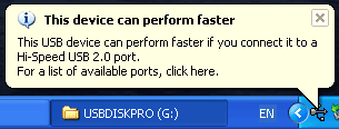
The looks like the most likely reason for the problems, not enough bandwidth - which would certainly explain the DTV issues. So I will have to try it on another PC...
As Captain Picard would say!

Wednesday, 16 May 2012
Ultra-cheap VHF-UHF Software Defined Radio

Over the last few months various forums and websites I visit have been buzzing with conversations about the RTL-SDR project (e.g Hackaday)
The idea is to take a cheap USB FM/DAB/DTV receiver (for less than £20) that contains a Realtek RTL2832U chipset and an appropriate tuner chip (such as the Elonics E4000) then by using new custom drivers you get yourself a SDR-Radio with a frequency range of around 64 – 1700 MHz
Sound familiar? Yes it is similar to the FUNCube Dongle.
There are a couple of limitations, unlike the FCD the device doesn't have a pre-amplifier so sensitivity might be limited. The IQ sampling is only in 8 bits so the dynamic range will be limited, but because the device doesn't use a USB Soundcard interface like the FCD to pass the IQ samples to the PC the sample rate can be much higher (theoretically 3.2 MS/s) which allows potential decoding of wideband signals which the FCD cannot do.
Over the last few week I have seen a few Youtube videos and read of peoples experiments so my curiosity was piqued and decided to get one to have a go.
There in lies the problem, since news of this hit the internet demand for suitable devices has rocketed and dealers are cashing in and prices have risen and stocks are low. Also as not every USB FM/DAB/DTV receiver has a suitable chipset it is very easy to buy one that won't actually work. There is a list of known working devices here and yesterday while browsing ebay I found a dealer claiming to be selling the Newsky TV28T for around £16 including postage so thought what the hell!
Should be arriving in the next few days so I will keep you posted!
Before I go I should point out that on some forums and discussion groups I visit that some are under the illusion that they are getting a high quality wide band receiver for peanuts and then have complained because they have got a unsupported device or don't understand how the software works. I am under no illusions it will undoubtedly be fiddly, unreliable and inaccurate but it should be FUN!
If nothing else I will have a way of listening to DAB and watching DTV on my PC, which is hopefully better than my last purchase (which I should really dig out and check what chipset it has!)
Tuesday, 15 May 2012
POCSAG and FLEX Decoding with the FCD
With today's modern mobile and wifi networks pagers might seem terribly old fashioned. But pagers are still in use today in places where mobile phones typically cannot reach and also in places where the operation of the radio transmitters contained in mobile phones is problematic or prohibited.
Whilst many of the national networks have closed down some are still going and some locations such as large hospitals have their own systems and are still popular with birdwatchers in Britain and Ireland with companies Rare Bird Alert and Birdnet Information offering news of rare birds sent to pagers that they sell.
Decoding pager messages using a PC involves some software and a receiver usually with a discriminator tap and using the sound card and/or a data-slicer. The most popular software is the PDW suite.
I decided to use the FUNCube Dongle to attempt some decoding as being able to keep everything digital within the PC rather than having audio leads from a scanner plugged into the soundcard meant no problems with audio circuitry messing up the signal. Also the ability to alter the bandwidth should mean I could get some excellent decoding - and I did, both the higher speed and more problematic FLEX and the easier POCSAG protocols.
Whilst many of the national networks have closed down some are still going and some locations such as large hospitals have their own systems and are still popular with birdwatchers in Britain and Ireland with companies Rare Bird Alert and Birdnet Information offering news of rare birds sent to pagers that they sell.
Decoding pager messages using a PC involves some software and a receiver usually with a discriminator tap and using the sound card and/or a data-slicer. The most popular software is the PDW suite.
I decided to use the FUNCube Dongle to attempt some decoding as being able to keep everything digital within the PC rather than having audio leads from a scanner plugged into the soundcard meant no problems with audio circuitry messing up the signal. Also the ability to alter the bandwidth should mean I could get some excellent decoding - and I did, both the higher speed and more problematic FLEX and the easier POCSAG protocols.
Tuesday, 1 May 2012
Rainy Sunday, Damp Monday SSTV
With the total washout at the weekend with very heavy rain on Sunday I was able to spend a decent amount of time monitoring. I recently brought a dry-cell adapter for the Alinco DJ-X10 receiver (EDH-16) allowing me to power it using normal AA Ni-MH batteries as the rechargeable battery pack it came with doesn't hold its charge any more.

So as the rain hammered on the window I decided to decode some SSTV images on the amateur bands. I connected up the discone and the computer tuned to 14.230Mhz USB and fired up MMSSTV. Some of the better decoded images I've got over the last couple of days are included below.
I did have an attempt at decoding some digital SSTV using EasyPAL but despite some strong signals couldn't quite get a full sync, but I think that was down to the conditions and the relatively poor rejection of the DJ-X10. With no ATU the out of band signals and nearby signals from what I suspect are high power operators were just too much for it, as the following sound file demonstrates.
Swamped SSTV by nerdsville


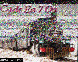

So as the rain hammered on the window I decided to decode some SSTV images on the amateur bands. I connected up the discone and the computer tuned to 14.230Mhz USB and fired up MMSSTV. Some of the better decoded images I've got over the last couple of days are included below.
I did have an attempt at decoding some digital SSTV using EasyPAL but despite some strong signals couldn't quite get a full sync, but I think that was down to the conditions and the relatively poor rejection of the DJ-X10. With no ATU the out of band signals and nearby signals from what I suspect are high power operators were just too much for it, as the following sound file demonstrates.
Swamped SSTV by nerdsville
Monday, 30 April 2012
The interference continues!
I am still suffering from that horrendous interference and am no nearer tracking down its source.
I have made another video showing the effects. As I mentioned before the signal seems to build in intensity and tends to drift frequency and then fade away. I know the FUNCube dongle filtering can be susceptible to out of band signals and images especially in the VHF but the video shows the same interference on a normal receiver with a different antenna.
Interestingly I have monitored a few local amateurs also mentioning problems with noise that has been affecting them, one even described an "annoying pulsing sound"
I have made another video showing the effects. As I mentioned before the signal seems to build in intensity and tends to drift frequency and then fade away. I know the FUNCube dongle filtering can be susceptible to out of band signals and images especially in the VHF but the video shows the same interference on a normal receiver with a different antenna.
Interestingly I have monitored a few local amateurs also mentioning problems with noise that has been affecting them, one even described an "annoying pulsing sound"
Subscribe to:
Posts (Atom)