Most GPS devices have a limit on the altitude they work at, normally 60,000 feet or less. This is a legacy of the now defunct CoCom (Coordinating Committee for Multilateral Export Controls) restrictions. For my HAB project this restriction needs to be disabled and the GPS must be switched into 'flight mode' In the HAB community the favoured devices are made by U-BLOX
Therefore when I was sourcing a GPS I had search specifically for a inexpensive device using a U-BLOX.
 s s |
| The GY-GPS6MV2 as supplied |
It is also available from domestic suppliers but often at a much more inflated price, but you don't have to wait several weeks for them to be delivered.
There are many other GPS modules available but this module seems to be one of the cheapest available. it is often listed as a NEO6MV2 GPS Module Aircraft Flight Controller.
The module consists of a small PCB 25mm x 35 mm size with a separate ceramic antenna connected by a small lead which is 25mm x 25mm in size. The Antenna is quite heavy and isn't suited to Pico HAB payloads but for other uses is more than satisfactory.
On the board is a small button-cell battery to provide backup to the GPS chip and a small EEPROM connected to the GPS chip which I believe can store configuration(s). I haven't used it myself just using the module in it's default set up at the moment. For a schematic click here
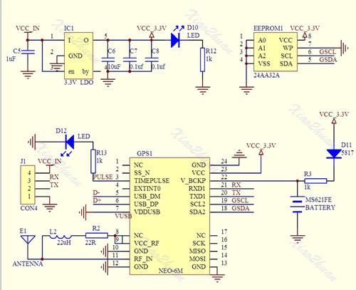
The board has four connectors VCC, GND, TX (Transmit) and RX (Receive) and can be powered by the 5V supply on Arduino boards since it has a small regulator to provide the 3.3V needed.
In most projects all that is required is data out of the GPS. The GPS TX (data out) being connected directly to the microcontrollers RX (data in) The (0V and 3.3V) level shift of the signal is compatible with the TTL input of the microcontroller.
The GPS by default will start up and output standard NMEA sentences at 9600 Baud, until GPS position lock is achieved the NMEA sentences won't have a long/lat location. The module also has an LED which will start flashing once a lock is achieved.
There is no direct connection for the highly accurate 1PPS (pulse per second) signal that can be used for frequency calibration, but the flashing LED is driven by pin 3 of the GPS module which is the 1PPS (pulse per second) signal required.
The 1PSS signal, like the TX is either 0V and 3.3V, in order to use it a small lead will need to be soldered onto the board, either directly onto Pin3 of the GPS chip, or alternatively on to the small current limiting resistor used by the LED, as indicated below.
 |
| Showing the GPS 1pps points |
No comments:
Post a Comment